
Solving Genset Electrical Issues…
Short of those in planes and rockets, I think electrical systems on boats are possibly the most complicated. The simplest cruisers have at least a small AC system and a slightly larger DC system on board. Large modern long-distance cruisers can have extremely complex AC power systems consisting of generator(s), and inverter(s) in addition to one or more shore power connections with potentially two different voltages (120 and/or 240). The DC systems can also get pretty complex when installed equipment dictates separate banks of batteries, multiple chargers, advanced alternator charging controllers, solar power, and/or wind generators also possibly supporting multiple voltages (6, 12, 24, etc). The point is that a single boat can have several different electrical systems that are all intertwined in various ways. This makes installing a system correctly quite difficult and troubleshooting a system even more so.
We’ve had our boat for nearly two months and as it is an 8-year-old vessel it has had several changes to the electrical systems onboard over its life. A generator, bow thruster, and two independent reverse cycle A/C systems were added. Aside from the additional equipment and wiring, we also now have 7 batteries in 4 banks. Luckily only the necessary factory wiring was touched and much of that wiring is still intact, but since we were not the owners when these changes were made, we don’t really know how it is all connected. In the past couple weeks of evening and weekend sailing I’ve come across three issues specific to the AC electrical system that needed to be handled sooner than later. All of these issues ended up being generator related.
Problem 1: The generator oil pressure gauge intermittently shows very HIGH oil pressure, past the last marked value on the gauge (80PSI). It seems to happen after the generator has been running for a while. All other gauges are showing normal values and it seems to be operating normally otherwise.
 Problem 2: The reverse polarity indicator is half-lit on both the incoming AC source panel and the primary AC circuit panel. This only happens with the generator is the source however. Neither shore power nor inverted power exhibit this.
Problem 3: I’ve twice brought my daughters nightlight table lamp down to the boat for an overnight stay and both times the bulb was burned out before bedtime. The first time I just assumed it was damaged during transport, but the second time I actually heard the bulb (7w/120VAC) pop as I plugged it in to the AC outlet (which is a GFCI outlet, more on that later). Aside from the bulb blowing out I haven’t seen any other issues with AC equipment on board (TV, Bose, HVAC, battery chargers, water heater, etc).
So I decided I’d start with an outlet wiring tester and multimeter and see if there’s something wrong with the outlet in the forward cabin or somewhere else. This morning, armed with all my electrical tools, I headed down to the boat for some troubleshooting.
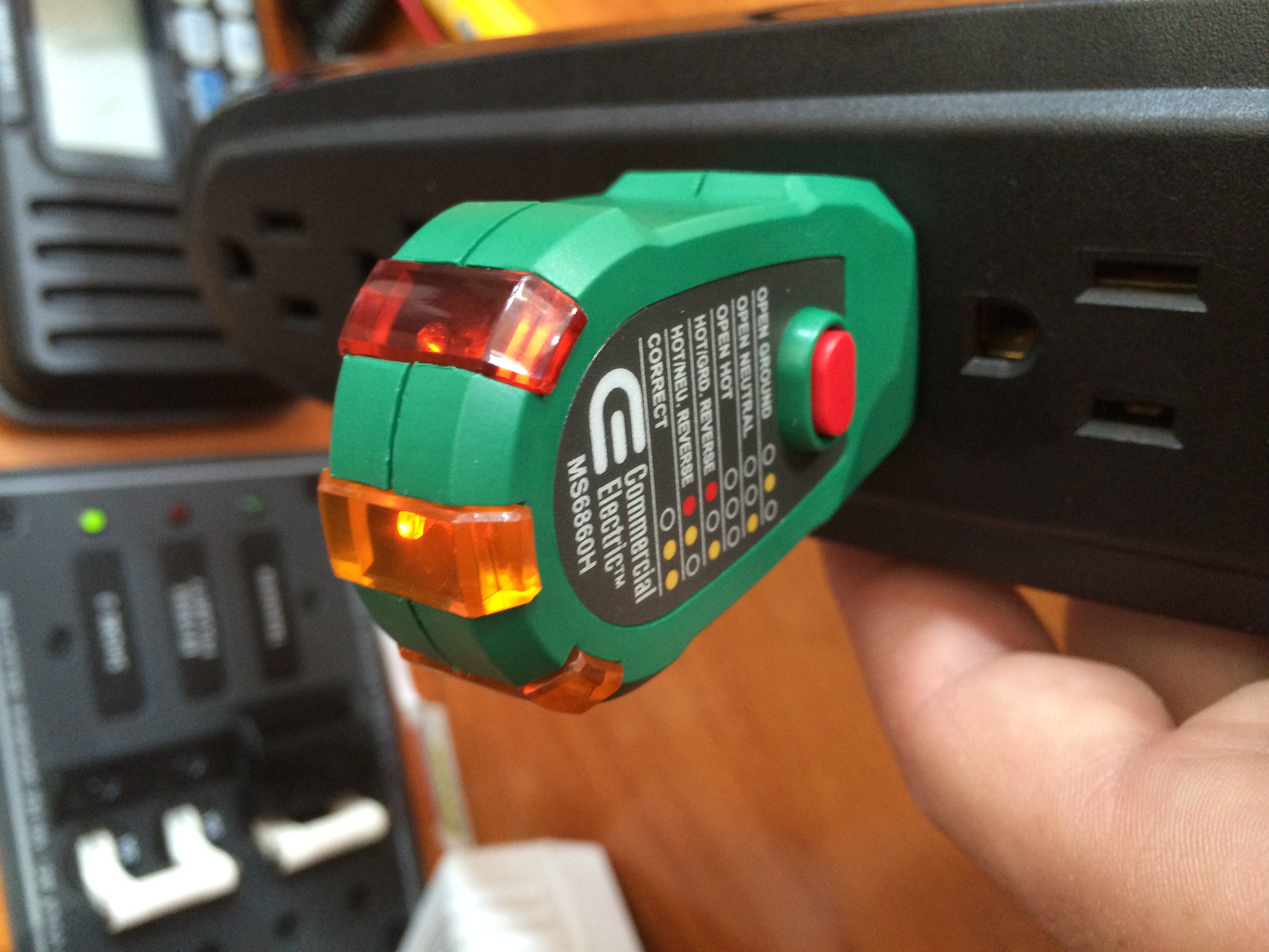
While still on shore power, I plugged the tester in to the outlet at the nav station and confirmed it ind icated a correctly wired outlet. Then I switched over to the generator and had a total WTF moment. It’s hard to see in this photo, but all three lights on the tester are lit. The confusion I had is in part because that particular light combination is not one of the possible combinations shown on the label or in the manual. Now what?
I moved the tester to the vberth outlet where the table lamp was previously connected and got the same result. In fact every outlet in the boat shows the same. The red button on the tester is for testing GFCI. When running on the generator, pushing that button does NOT trip the GFCI circuits on the outlets. It DOES work fine when on shore power.
Based on how the panels operate, it appears that the AC power from the source selection panel feeds the factory AC panel, which then feeds the Xantrex charger/inverter, which comes back and feeds the AC outlet circuits on the same AC panel. Even with all AC circuits powered off the reverse polarity light is lit on the panels when the Generator source is switched on.
Open her up!
At this point I removed pretty much every cushion, settee board, and opened up the electrical panels and genset sound box. I then killed the DC power, shut down the breakers AT the shore power connections and started checking for voltage between the neutral and ground on the AC circuits. The multimeter showed ~70VAC or ~30VAC between the neutral and ground depending on where I tested. When I shut off the generator source at the panel and check on the line side of the breaker, I got 0VAC between neutral and ground, but ALSO 0VAC between hot and ground which I didn’t expect.
I traced the 3 AC lines from the generator all the way to the panel to confirm how it was connected and it clearly connected as expected. I have all the factory wiring diagrams for the boat as well which helped some but didn’t give me any more insight. All I could think of was that the problem had to be between the generator and the source selection panel.
 Back to the genset I opened up the electrical connection box and then pulled up the wiring diagram from Northern Lights on my laptop–something was amiss. Of the 3 wiring options provided for the OM672L2.3, none of them matched what I saw in the box. The 120V AC diagram looked the closest but the ground(green) wire was not where it should be, assuming I was reading everything correctly.
Again, no voltage between  hot and ground or neutral and ground. It was time to get some advice. I called Paul Leask (Service Manager at Northern Lights Corporate) and explained to him my symptoms, and the differences between the wiring I see and the diagram I was looking at. Before I even finished describing Paul already knew what was wrong. Basically on my unit, the ground wire from the AC panel was connected to a stud inside the box, effectively grounding it to the box itself.
There are two issues here. One is that the box is electrically isolated from the rest of the generator, so the connection point is more or less useless, and two, the ground and neutral need to be bonded together at the generator connection points.
Slight Digression: Paul explained that Northern Lights leaves the bonding of neutral to ground up to the customer. It’s noted in the wiring diagrams/owners manual as “recommended” but apparently there are two schools of thought here as to how to handle the ground and some people believe it’s incorrect to bond them. Essentially if they pre-wired it, 50% of their customers would see it as incorrect, and as they ship them today with the bonding not pre-wired about 50% of their customers see it as being needed. Lose-Lose I guess. Since the manufacturer recommended it both on the phone and in print, and I clearly had some wiring issue, I opted to rewire it per the recommended practice.
 First I moved the existing ground wire out of the box and grounded it to the generator chassis. Then I ran a new ground from the same chassis point up to the box. Then I connected that end to the V2 terminal inside the box,
  which is electrically connected to V1 where the neutral line is attached. After securing these connections I stepped through the process of firing everything back up piece by piece while testing. Voila! No more reverse polarity lights, outlets that test as properly wired, AND GFCI outlets that trip as expected.
To bond or not to bond?
Interestingly I got a few comments on the Facebook Liveaboard Sailboats group telling me that bonding the neutral and ground is a bad idea. I did a little bit of research and I believe I understand why it IS needed here AND why people think it’s incorrect..
First, I found an article online discussing why certain generators didn’t work to power up RVs (http://www.noshockzone.org/generator-ground-neutral-bonding/) and it actually made a bunch of sense. One key point: “..an NEC and RVIA code requirement that the safety ground wire never carries any load current, and there can be only one Ground-To-Neutral bonding point in any distributed electrical system in the USA…” In a shore power system, the ground and neutral are bonded back on shore and such there is no need to ( and in fact you should NOT) bond the two legs inside the boat. However, when you are not on shore power, this means there is no neutral to ground bond in place anywhere in the boat. When the genset is the source, the boat’s AC system is cut off from shore and not getting the benefit of the on-shore bond. So a bond at the generator needs to exist. In my case it was not bonded when it was installed.  Nigel Calder’s book also discusses this on page 134 of the Boatowner’s Mechanical and Electrical Manual (3rd Ed) and provides this handy diagram.
So based on all this reading, I’ve come up with the following rules for bonding neutral to ground in boat AC systems…
- When on shore power, the boat’s AC electrical system should *NOT* bond neutral to ground
- When NOT on shore power, the onboard AC power source *SHOULD* have neutral to ground bonded as close to the power source as possible.
- Ensure that the bond on an onboard AC source is not connected to the rest of the AC system when Shore power is connected.
- Somewhat related, ensure that the AC Ground and DC Ground are connected together.
As for problem #1, the oil pressure gauge was intermittent because the wire was loose on the oil pressure sending unit. Solved!
Also, kudos to Northern Lights and Paul for taking my call on the fly and answering questions over the phone.


